Hollow Shaft vs Solid Shaft Encoders: Which Design to Choose?
20.11.2026
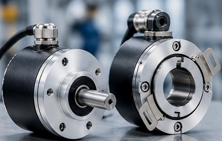
In industrial automation systems, CNC machine tools, conveyor systems, and robotic cells, rotary encoders continuously monitor the angular position, speed, acceleration, and rotational direction of shafts. When designing a kinematic layout or upgrading a drive system, engineers must choose between two physical configurations: hollow-shaft vs solid-shaft encoders. At first glance, both types perform the same electrical function, converting rotation into a series of pulses or a digital code. However, their mechanical interface with the drive mechanism differs fundamentally.
The design defines the construction of the housing and the entire kinematic chain of the drive. Unlike a hollow-shaft encoder, a solid-shaft encoder must use an intermediary coupling element to connect it to a rotating shaft of a machine.
Choosing between these encoder designs influences such assembly parameters as dimensions of the final product, requirements for shaft machining precision, tolerances to misalignments, limits of vibration, and installation and operation complexity. But electromechanical characteristics, such as resolution of measurement, type of output stage, and data transmission protocols, are selected separately from the mechanical design of the housing.
What Is a Solid Shaft Encoder?
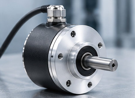
A classic solid shaft encoder features its own integral shaft, which protrudes from the housing and is supported by internal precision rolling bearings. To transmit rotation from the actuating mechanism to the encoder's measuring disk, the shaft must be rigidly coupled to the equipment's rotating shaft.
In real-world conditions, perfect alignment between two independent rotating axes is unattainable due to manufacturing tolerances, assembly errors, and thermal deformation. Consequently, a direct, rigid connection between the machine shaft and the encoder shaft is not permissible. The kinematic link is always established via a compensating element:
Machine shaft → Compensating coupling → Encoder shaft
The encoder housing itself must remain completely stationary relative to the machine frame. Specialized mounting flanges (such as synchro, clamping, or square flanges) and rigid brackets are used to secure it. In heavy machinery manufacturing, pulp and paper production, and conveyor systems, solid shaft rotary encoders are used to measure motion parameters on electric motors, process rollers, gearboxes, and transmission mechanisms.
Advantages of solid shaft encoders
- Flexible mounting options. The use of various flange types, adapter plates, and installation brackets simplifies the solid shaft encoder mounting on machine frames of any configuration;
- Bearing protection via coupling. An external compensating coupling absorbs angular, radial, and axial shaft misalignments, isolating the encoder bearings from damaging bending moments;
- Independence from machine shaft diameter. Encoder spindle dimensions are not tied to the drive shaft size, allowing for the standardization of sensors used across the facility;
- Convenient scheduled replacement. If the encoder is damaged, you can remove it without disassembling the equipment's main drive shaft.
Limitations of solid shaft encoders
- Increased axial footprint. The coaxial mounting of the sensor, coupling, and mounting bracket requires significant clearance along the axis of rotation;
- Additional transmission elements. The use of an encoder coupling complicates the kinematic layout, increasing the moment of inertia and the overall assembly cost;
- Risk of bearing overload. Incorrect coupling selection or exceeding misalignment limits leads to radial forces that can damage the bearing assembly;
- Numerous maintenance points. Maintenance personnel must regularly check the tightness of threaded connections on the coupling, flanges, and mounting brackets.
What Is a Hollow Shaft Encoder?
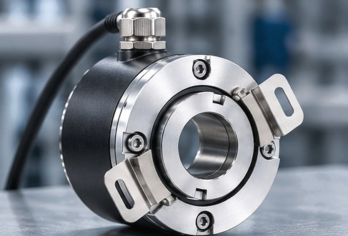
A design utilizing a hollow shaft encoder completely eliminates the need for a protruding external spindle. The center of the device housing features a through-bore or blind bore equipped with a precision internal sleeve and supported by bearings. The encoder mounts directly onto the equipment's rotating shaft, establishing a direct mechanical connection.
Using a hollow bore encoder eliminates the need for external couplings and adapter sleeves:
Machine shaft → Encoder hollow bore
Installing a hollow shaft rotary encoder ensures maximum drive compactness. Based on their internal bore design, these encoders fall into two main categories.
Blind hollow shaft encoders
In design, a blind hollow shaft encoder features a bore closed off at the rear by an internal wall within the housing. The machine shaft inserts into the sleeve to a precise depth until it reaches a mechanical stop. This blind design prevents the ingress of dust, moisture, and process contaminants from the rear of the housing, thereby protecting the optical or magnetic sensing system.
Through hollow shaft encoders
A through hollow shaft encoder features a central bore that passes entirely through the housing. This design allows the device to be mounted at any point along a long drive shaft and enables the routing of additional pneumatic lines, hydraulic hoses, or electrical cables through the center of the housing.
To transmit torque, the encoder's inner sleeve is rigidly secured to the machine shaft using a split collet clamp, a clamping ring, or set screws. Meanwhile, the device's outer housing is prevented from rotating by a flexible compensating element like a torque arm or a flat spring plate. The torque arm anchors the housing to the machine frame while simultaneously compensating for minute shaft runout and radial play.
Advantages of hollow shaft encoders
- Direct drive mounting. The absence of external couplings eliminates backlash, reduces torsional deformation, and increases the rigidity of the feedback loop;
- Minimal axial dimensions. Direct hollow shaft encoder mounting is an optimal choice for applications with drive length constraints;
- Lowered number of components. The reduced use of adapter flanges and couplings minimizes the number of mechanical joints and decreases inertia in the system;
- Compatibility with electric motors. This device is compatible for installation on the rear shaft extension of a servo motor or an induction motor;
- Fast installation. It is mounted simply by tightening one clamping ring and fixing the torque arm.
Limitations of hollow shaft encoders
- The mounting sizes must be exactly right. The bushing's diameter must match the diameter of the machine shaft, allowing for tolerances.
- The quality of the shaft's surface matters. The roughness of the shaft, eccentricity, and variations from a cylindrical shape all affect the durability of the bearings in the sensor.
- The vibrations from the shaft affect everything. The moving parts of the machine shaft impact the internal elements of the encoder.
- Requirements for how the torque arm should be fixed. Fastening the anti-rotating mechanism keeps the housing from easy floating movement, and it wears out quickly.
Hollow Shaft vs Solid Shaft Encoders: Key Differences
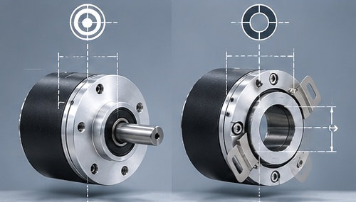
A comparison of essential characteristics reveals how design features influence the device's integration into the equipment. When considering the main shaft encoder types, an engineer must weigh kinematic requirements against the available space.
|
Feature |
Hollow Shaft Encoder |
Solid Shaft Encoder |
|
Mechanical connection |
Fits over machine shaft |
Connected through coupling |
|
Separate coupling |
Usually not required |
Usually required |
|
Axial installation space |
Generally lower |
Generally higher |
|
Shaft compatibility |
Bore must match shaft |
Determined by shaft and coupling |
|
Alignment considerations |
Directly affected by machine shaft |
Coupling can compensate for limited misalignment |
|
Mounting |
Clamp + torque support/appropriate mounting |
Flange/bracket + coupling |
|
Mechanical components |
Fewer |
More |
|
Typical use |
Motors, compact machinery, direct shaft mounting |
General machinery, external shaft feedback |
How Mounting Design Affects Encoder Installation
Installation is a critical stage that determines the actual service life of the bearings and the stability of the output signal.
Couplings and alignment
Proper selection and placement of couplings is vital for solid shaft machinery. Three kinds of misalignment that occur in operation are:
- Angular misalignment. The intersection of the axis of machine shafts with the axis of the encoder;
- Parallel misalignment. Where shafts are misaligned parallel to each other;
- Axial misalignment. The movement of the axis of the shafts in relation to each other due to thermal expansion.
If misalignment angles exceed permissible levels, bending moments are created. This results in increased wear of bearing tracks, vibration, and distortion of pulses. Use of gear, bellow, or diaphragm couplings allows for any deviations.
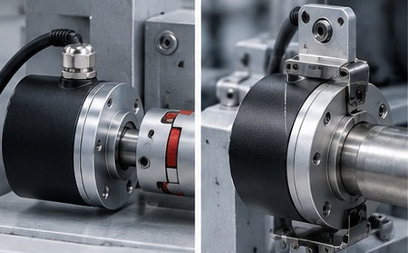
Hollow shaft mounting
Proper installation of a hollow-shaft encoder requires strict adherence to the installation procedure:
- Verifying the machine shaft diameter against ISO tolerances (h6 or g6) and ensuring the absence of burrs;
- Smoothly fitting the encoder sleeve onto the shaft without using impact tools;Tightening the collet or clamping ring components to the specified torque;
- Installing the flexible torque arm without inducing radial preload;
- Checking radial and axial runout using a dial indicator.
Expert note. Do not think that mounting directly solves alignment issues. A hollow-shaft encoder may still be influenced by excessive runout, improper clamping, or bad torque-arm installation.
When to Choose a Hollow Shaft Encoder
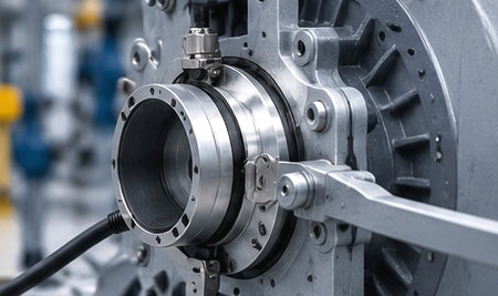
Hollow-shaft designs are most effective under the following conditions:
- The machine design allows the encoder to be fitted onto an accessible shaft end;
- Equipment dimensions are strictly limited in terms of length;
- Minimizing mass, inertia, and the number of components is a priority;
- The equipment shaft diameter matches standard encoder bore sizes;
- The sensor is mounted on the rear shaft of an electric motor or servo drive.
Typical applications include:
- Servo motors and vector-controlled induction motors;
- Conveyor system drive rollers;
- Robotic joints and rotary tables;
- Automated packaging and printing machinery;
- Lifting mechanisms and winches.
When to Choose a Solid Shaft Encoder
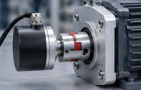
A solid-shaft configuration is technically justified in the following situations:
- Direct shaft mounting is impossible due to high temperatures, contamination, or the absence of a free shaft end;
- Rigid mechanical decoupling between the drive and the sensor is required;
- Standard flange mounting interfaces are provided on the equipment frame;
- Rotational transmission is achieved via measuring wheels, gears, or belt drives;
- An obsolete sensor is being replaced on an existing production line.
Typical application examples:
- Spindles and slides of CNC metalworking machines;
- Heavy-duty rolling mills and papermaking machines;
- External linear displacement measurement systems using cable-extension mechanisms;
- Dynamometer test stands;
Equipment operating in environments subject to constant aggressive wash-down procedures.
What Else to Check When Choosing an Encoder
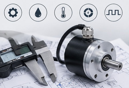
Choosing between a hollow and a solid shaft is just one step in the selection process. To ensure the device operates reliably and integrates correctly into the system, other specifications must also be considered.
Practical checklist:
- Encoder type. Choice between incremental and absolute versions;
- Shaft dimensions. Diameter and mechanical mounting/fit;
- Resolution. PPR or CPR values, or the number of bits/positions, depending on the device type;
- Output interface. Compatibility with standards such as TTL, HTL, push-pull, SSI, BiSS, CANopen, or Industrial Ethernet;
- Supply voltage. Compatibility with the control system;
- Maximum speed. Shaft rotation speed limit (RPM);
- Mechanical loads. Permissible axial and radial loads;
- Protection rating. Housing protection against dust and water ingress;
- Operating temperature. Expected equipment and ambient operating conditions;
- Vibration and shock. Resistance to stresses associated with heavy industrial equipment;
- Cable and connector. Orientation, connection type, and available mounting space.
To select a reliable device for your application, explore the industrial encoders in our equipment catalog.
Common Mistakes When Choosing Between Hollow and Solid Shaft Encoders
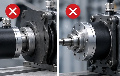
An analysis of operational practice reveals the most common errors:
- Selecting a unit based on electrical parameters without first analyzing the mechanical mounting;
- Ordering a device with an unsuitable bore diameter or bore tolerance;
- Ignoring misalignment and using rigid couplings for solid shafts;
- Using non-specialized couplings with low torsional rigidity;
- Exceeding permissible radial loads on the spindle caused by belt drives;
- Rigidly fixing the hollow shaft's torque arm, thereby preventing the housing from self-aligning;
- Mounting the device on a shaft that exceeds permissible radial runout limits;
- Selecting a replacement based solely on shaft diameter without considering the output stage type;
- Specifying an excessively high PPR resolution, leading to controller counter input overload;
- Failing to account for signal cable bend radius in confined spaces.
Expert insight. When choosing between hollow and solid shaft models, always begin by analyzing the mechanical connection. Evaluate the machine shaft parameters, available space, and unavoidable misalignments and vibrations. Once the kinematic layout is established, select the resolution, interface, speed specifications, and protection class to match your control system requirements.