How to Choose the Right Encoder Resolution for Industrial Applications
28.10.2026
Selecting the correct rotary encoder resolution is a crucial step in the design of motion control, automation, and electric drive systems. Encoder resolution essentially determines the minimum increment of angular or linear movement that a feedback sensor can detect and transmit to the controller. A common engineering mistake is the misconception that installing a high-resolution encoder automatically guarantees superior positioning accuracy, smooth operation, and perfect equipment operation.
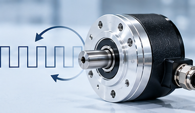
Selecting the appropriate encoder PPR value requires a comprehensive consideration of the kinematic diagram, shaft speed, PLC input bandwidth, and machine process requirements.
Today we’ll cover;
- What PPR, CPR, and counts per revolution mean.
- How to calculate the resolution needed for a specific application.
- How encoder resolution affects position and speed measurement.
- Why shaft speed and controller frequency limits matter.
- How to avoid over- and underspecifying encoder resolution.
What Is Encoder Resolution?
Encoder resolution describes how finely an encoder can divide one revolution into measurable positions. Incremental encoder resolution is commonly expressed in pulses per revolution (PPR), while absolute encoder resolution is often specified in bits or positions per revolution.
When analyzing a parameter such as rotary encoder resolution, a 360-degree circle is divided into a specific number of measurement segments. In incremental systems, incremental encoder resolution is typically specified in PPR, which denotes the number of rectangular pulse periods per shaft revolution. In absolute encoders, resolution is expressed in bits, or the number of unique code positions per revolution.
PPR, CPR, and Counts per Revolution Explained

The terminology used by manufacturers is often confusing due to the lack of a uniform standard in the documentation.
PPR – pulses per revolution
The PPR designation indicates the number of complete square wave periods on one electrical channel per complete shaft revolution. Encoder PPR in technical catalogs defines the basic physical characteristic of an optical disk raster or magnetic scale.
CPR – counts per revolution
The abbreviation CPR can stand for counts per revolution or cycles per revolution, depending on the manufacturer. In some specifications, CPR is completely equivalent to PPR, while in others it denotes the total number of logical states after decoding.
Quadrature counting
A standard incremental encoder generates two channels with a 90-degree phase shift. The controller can capture the pulse rise and fall times of both channels, quadrupling the resolution. For example, with a PPR of 1024, quadrature processing yields 4096 counts per revolution.
Start With the Measurement Requirement
Before selecting a PPR, you should determine the primary function of the sensor in the control loop.
Speed measurement
When changing speed, the controller measures the time between pulses or their number per fixed cycle. At low speeds, low resolution leads to data exchange delays and torque pulsations.
Position measurement
For positioning applications, the sensor must provide resolution that matches the mechanism's tolerances. The required rotary encoder resolution is calculated taking into account the ball screw pitch, drum diameter, and gear ratio.
Motion control
In servo drive circuits, feedback affects the dynamics and noise level of the electric motor. Insufficient encoder resolution causes noise when calculating the velocity derivative, creating hum and motor heating.
Field insight. “I don’t start by asking how much resolution I can get. I start by asking how much resolution the machine actually needs.”
How to Calculate the Required Encoder Resolution
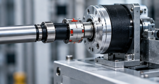
Mathematical encoder resolution calculation allows you to translate mechanical requirements into electrical impulses.
Angular resolution
Angular resolution is defined as the smallest angle of rotation that the system can accurately measure. This value is calculated by dividing 360° by the total number of counts. For instance, at 1024 counts, the angle for each measure equals 0.3516°, while at 4096 it becomes 0.0879°.
Linear movement
In case the measuring wheel is used, the formula for determining the linear movement becomes the circumference of the wheel divided by the number of pulses. If the circumference of the cylinder wheel is equal to 500 mm and the number of counts amounts to 2000, then the result is 0.25 mm.
How Much PPR Do You Actually Need?
| Task |
Required Level |
Primary Goal |
|
Simple RPM checking |
Low |
Basic speed readout |
|
Conveyors and belts |
Medium |
Movement tracking |
|
Standard motor drives |
Medium to high |
Smooth motion |
|
Position control machines |
High |
Accurate positioning |
|
CNC and robotics |
Very high |
Precise motion control |
When selecting an encoder PPR value, it's best to rely on proven practical ranges:
- 100-500 PPR range. Simple speed monitoring and operation at medium and high speeds.
- 1000-2048 PPR range. General industry standard for asynchronous motors, conveyors, and basic automation.
- 5000+ PPR range. Selectable when installing a high-resolution encoder for robotics, CNC machines, and precision rotary tables.
How Shaft Speed Affects Resolution Selection
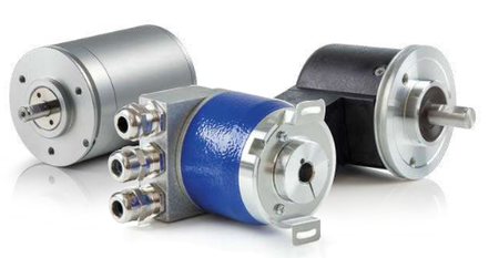
Higher encoder PPR combined with high shaft speed produces a higher encoder pulse frequency, so encoder resolution must remain within the input-frequency limits of the PLC, drive, or motion controller.
Calculation formula: encoder pulse frequency (Hz) = encoder PPR × RPM/60.
For example, a 2048 PPR encoder at 3000 RPM generates a frequency of: 2048 × 3000/60 = 102400 Hz (102.4 kHz).
Why Higher Resolution Is Not Always Better
Using excessively high resolution entails several significant disadvantages:
- High pulse frequency. The encoder pulse frequency increases the risk of pulse loss during long-distance transmission as it increases.
- Controller load. Processing millions of edges per second overloads the PLC's computing module.
- Input limitations. Exceeding the maximum frequency of the counting input leads to positioning errors.
- Sensitivity to interference. High-frequency signals are more vulnerable to electromagnetic interference from frequency converters.
- Unnecessary financial costs. Installing an unreasonably high-resolution encoder increases the cost of the project without providing any real benefit to production.
- Mechanical limitations. If the system has 1 mm of backlash, a resolution of 0.001 mm will not make the machine more accurate.
Encoder Resolution vs Accuracy
Higher encoder resolution provides finer measurement increments, but it doesn’t automatically improve the encoder accuracy or physical precision of the complete motion system.
In engineering practice, it is important to clearly distinguish between the terms resolution, accuracy, and repeatability.
Resolution
Resolution is the minimum displacement increment that a sensor can detect and transmit to the system.
Accuracy
The encoder accuracy parameter determines the deviation of the measured position from the actual physical shaft angle.
Repeatability
Repeatability characterizes the system's ability to return to the same point after repeated movements.
The following factors affect the final accuracy of the system:
- Backlash in gear reducers and couplings.
- Shaft misalignment and thermal deformation.
- Elastic deformation of structures under load.
- Mounting errors and backlash in bearings.
Consider the Mechanical System
Each kinematic element changes the resulting output resolution. When performing calculations, you need to take into account the gear reduction, pulley diameters, and screw pitch. If a sensor is installed on the motor shaft before a 10:1 gearbox, its resolution at the gearbox output will increase tenfold. However, the gearbox backlash will not be detected by the sensor, which will reduce the actual accuracy of the entire system.
Check Controller and Signal Compatibility
Before purchasing equipment, it is necessary to verify the electrical parameters:
- PLC input frequency limit. Ensure that the encoder pulse frequency does not exceed the counter's capabilities.
- Output signal type. Select between Line Driver (TTL/RS-422) for long lines and HTL for 24V logic.
- Supply voltage. Matching signal levels between the sensor and the receiving module.
- Wire length. Minimum cable length for high frequency signal attenuation.
Common Encoder Resolution Selection Mistakes
|
Mistake |
Possible Result |
Better Approach |
|
Choosing highest PPR |
High cost and signal overload |
Calculate actual needs |
|
Ignoring max speed |
Signal frequency too high |
Check frequency at max RPM |
|
Confusing PPR and counts |
Calculation errors |
Verify vendor definitions |
|
Ignoring controller limits |
Missed pulses and lost position |
Check controller input limit |
|
Confusing resolution with accuracy |
Unrealistic precision expectations |
Evaluate total system accuracy |
|
Ignoring gear ratios |
Wrong resolution at the load |
Include transmission ratios |
|
Choosing too low resolution |
Poor speed and motion control |
Calculate minimum required value |
How to Choose the Right Encoder Resolution
The sequential selection algorithm includes the following steps:
- Defining the task. Clarifying the primary function of the encoder – speed control or positioning.
- Calculating the required resolution. Determining the minimum travel step based on machine drawings.
- Considering kinematics. Including the ball screw pitch, pulley, and wheel diameters in the calculation.
- Gear ratio. Multiplying or dividing pulses by the reduction factor.
- Calculating the number of counts. Performing a formula-based encoder resolution calculation for the encoder shaft.
- Determining RPM. Recording the maximum shaft RPM.
- Calculating the signal frequency. Determining the peak encoder pulse frequency.
- Checking PLC inputs. Matching the operating frequency with the PLC counter bandwidth.
- Refine specifications. Checking the encoder PPR definition in the manufacturer's documentation.
- Interface selection. Selecting the output type (TTL or HTL) for the noise environment.
- Mechanical evaluation. Comparing the obtained resolution with the overall encoder accuracy of the mechanism.
- Final selection. Selecting the lowest pulses per revolution value that satisfies all conditions.
Expert insight. “I usually choose enough resolution to give the controller reliable feedback with a reasonable margin. Going far beyond what the mechanics and control system can use rarely improves the machine.”
FAQ
What does PPR mean on an encoder?
PPR stands for pulses per revolution and denotes the number of full pulses in one shaft rotation. The controller uses these pulses to accurately calculate the speed, acceleration, and current position of the actuator. The higher the value, the more measurement marks are printed on the device's optical disk.
Is higher PPR always better?
Choosing the maximum PPR value isn't always the optimal solution for industrial equipment. This can lead to a sharp increase in the encoder pulse frequency at high speeds. If the frequency exceeds the PLC input limit, the system will begin to skip pulses and lose position.
How do I calculate encoder resolution?
A proper calculation begins with determining the minimum pitch the machine must capture. For rotary axes, 360° must be divided by the required number of counts, taking into account quadrature decoding. For linear motion, the travel distance per revolution is divided by the total number of counts. The resulting value is divided by four when using x4 decoding to determine the required PPR.
What PPR should I use for a motor?
Selecting the appropriate PPR for an electric motor depends on the required speed range and drive type. For general-purpose asynchronous motors, a resolution of 1000 to 2048 pulses is considered standard. In simple fan and pump systems, a range of 256 to 500 PPR may be sufficient.
What encoder resolution is suitable for a conveyor?
Conveyor systems typically do not require a high-resolution, high-end encoder. For speed control and load positioning on a belt, a PPR in the range of 500 to 1024 is sufficient. When using a measuring wheel with a circumference of 500 mm, a 1024-pulse encoder provides a resolution of approximately 0.12 mm.
What is the difference between PPR and CPR?
The difference between the terms PPR and CPR often depends on the specific documentation of a particular manufacturer. PPR typically refers to the number of square wave periods on a single physical channel. CPR often refers to the total number of samples after quadrature processing of all A and B signal edges.
Does higher encoder resolution increase accuracy?
Increased encoder resolution does not automatically improve the actual accuracy of a mechanical system. Resolution only determines the minimum measurement step, while encoder accuracy indicates the deviation from the true coordinates.
How does rpm affect encoder pulse frequency?
The shaft speed directly affects the final pulse frequency of the encoder. This relationship is linear and is calculated by multiplying PPR by RPM and dividing by 60. As the motor speed increases, the pulse repetition rate at the controller inputs increases proportionally.
Can encoder resolution be too high for a PLC?
The resolution parameter may be too high for a specific PLC. Each counter input module has a hard-coded signal processing frequency limit. If the frequency exceeds this threshold, the PLC will skip pulses and accumulate position error.
How does a gearbox affect encoder resolution?
Installing a gearbox between the encoder and the load significantly changes the effective rotary encoder resolution. If the encoder is located on the motor shaft before a 10:1 gearbox, its physical resolution at the gearbox output increases tenfold.