Common Encoder Installation Mistakes and How to Avoid Them
22.09.2026
Sensors used in motion control and automation systems must have high reliability for the overall performance of the system to be good. Even the most expensive high-resolution sensor will not perform properly if it is installed incorrectly. Proper installation of the sensor is therefore as important as its proper selection and sizing.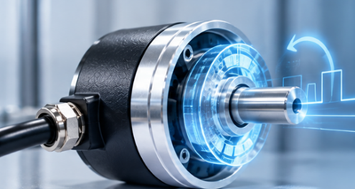
Errors made in mechanical assembly and electrical connections give rise to many adverse repercussions. Mechanical distortion produces undue strain on the bearing units, while badly laid out cabling is responsible for the electromagnetic interference. Therefore, the system experiences constant digital signal distortion, uncontrolled jitter, zero-point shifting, and early malfunction of devices.
According to service experience, in most cases, engineers find either a hardware failure or sensor breakdown to be the cause of a breakdown due to installation failures. In particular, all failures occur because of the shaft alignment tolerance violation, fastening bolts under-tightened or overtightened, grounding resulting in closed ground loops, and mistakes in designing couplings.
Today we will discuss:
- The most common mechanical and electrical encoder installation mistakes;
- How poor mounting, alignment, wiring, and grounding affect encoder performance;
- Practical solutions to improve accuracy, reliability, and service life;
- Troubleshooting tips for unstable signals, missed counts, and premature failures;
- Includes real-world examples, installation best practices, and engineer recommendations.
What Is a Rotary Encoder?
A rotary encoder converts shaft movement into electrical signals, allowing industrial automation systems to monitor position, speed, and direction with high accuracy.
A modern rotary encoder is a specialized electromechanical device designed to convert the angular position or mechanical movement of a shaft into a series of digital or analog electrical signals. Based on the received data, control controllers calculate the current position, direction of rotation, angular velocity, and acceleration of the drive.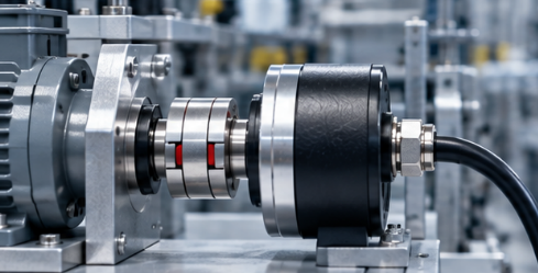
These sensors are main components in closed-loop motion control systems, servo drives, CNC machine tools, and robotic systems. To ensure high-precision automation, industrial rotary encoders are used, allowing for highly granular motion parameter tracking.
Why Proper Encoder Installation Matters
The measurement accuracy provided by a feedback sensor is directly determined by the mechanical stability of its connection to the driven shaft. If microscopic runout or radial misalignment is allowed during installation, the optoelectronic disk or magnetic sensor inside the housing begins to shift relative to the reading head. This leads to periodic step reading errors, which in turn reduces the overall positioning accuracy of the entire machine.
The reliability of the transmitted signal is also inextricably linked to the quality of the electrical installation. The use of shielded wires, proper housing grounding, and the absence of contact with power lines guarantee a high signal-to-noise ratio. Any interference in the measuring line will be interpreted by the PLC counter module as false pulses, disrupting the system calibration.
The service life of the measuring instrument's bearings is extremely sensitive to external mechanical loads. The sensor bearing assemblies are designed to withstand minimal radial and axial forces. If constant static voltage occurs during rigid shaft coupling, the bearing grease quickly burns out, the balls become deformed, and the sensor fails due to shaft seizure.
Correct installation influences overall performance and avoids unwanted downtime. If a high-speed machine or rolling line experiences an emergency stoppage because of a feedback sensor failure, it leads to a considerable loss of money, which is more than the value of the measuring device.
Field insight. “A perfectly selected encoder can still perform poorly if it’s installed incorrectly. Installation quality often determines long-term reliability.”
Mistake #1: Shaft Misalignment
Misalignment between the sensor shaft and the actuator drive shaft is the most common cause of mechanical damage to equipment. Even if the misalignment appears imperceptible to the naked eye, at high speeds it creates enormous dynamic loads: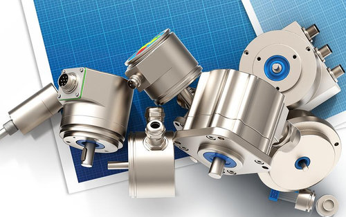
- Angular misalignment occurs when the axes of rotation of the drive shaft and sensor intersect at an angle other than zero. This creates cyclic bending moments with each revolution. The optical disk inside the sensor begins to rotate at an angle, which over time leads to mechanical friction against the inner mask or housing.
- Radial misalignment takes place when the axes of the shaft are parallel but offset from one another. When the shaft is moving, the rotation creates a significant axial force. The radial force is transmitted directly to the bearing and results in local overheating, micro-dents on the surfaces of the bearing, and even damage to the cage.
- Axial movement (or motor shaft play) occurs due to the thermal expansion of metal and/or the features of drive design. If the sensor has been mounted rigidly without allowing for axial movement, the motor shaft will push against the sensor’s inner components in the direction of its axis, creating damage to the bearings and sensor elements.
All the misalignment types in question lead to quickly worn bearings, strain on the shaft’s metal, distortion of the signal, and malfunction of the bearings. To avoid this, one needs to use the systems for measuring distance or the systems for laser alignment as well as the compensating connectors.
Mistake #2: Choosing the Wrong Coupling
If you will get an inappropriate couplings or attempting to use a rigid shaft connection without a compensator will lead to serious engineering errors in the design and assembly of the unit.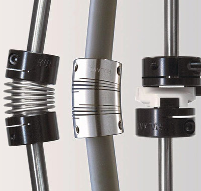
Let's look at the different types of couplings:
- Rigid couplings transmit torque without any backlash, but they do not compensate for runout at all. Their use is only permissible with perfectly laser-aligned shafts mounted on a common precision base. In other cases, using a rigid coupling will immediately overload the sensor shaft.
- Flexible couplings are manufactured using spiral slots in a metal cylinder. They perfectly dampen small vibrations and compensate for minor angular deviations, but have a limited torsion under sudden reversing loads.
- Bellows couplings made of thin-walled stainless steel provide the highest torsional rigidity with excellent compensation capacity in all three axes. This is the ideal choice for servo drives where backlash is critically absent and response speed is required to be maximized.
- Oldham couplings consist of three discs and handle large radial misalignments exceptionally well. The intermediate polymer slider dampens vibrations and electrically isolates the shafts from each other, preventing stray currents from flowing through the bearings.
Selecting the coupling type should be done strictly based on the misalignment tolerances, maximum operating speed, and torsional stiffness requirements of the specific drive.
Mistake #3: Incorrect Mounting
Incorrect fastening of the sensor housing to the supporting structure creates conditions for resonant vibrations and mechanical stress.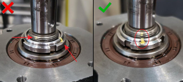
Excessive tightening of the mounting screws causes deformation of the flange and housing. Changes in housing geometry lead to displacement of the internal optical elements relative to each other. When pressing in couplings or pulleys, it is strictly prohibited to apply impact loads to the sensor shaft, as this will inevitably destroy the internal glass disk or damage the bearing assembly.
Using weak, thin, or homemade mounting brackets causes the structure to resonate during motor operation. Constant vibration is transmitted to the sensing element, causing severe signal jitter and premature mechanical wear.
Loosening of threaded connections during operation due to the lack of anaerobic thread locking agents will lead to gradual displacement of the sensor, the development of play, and a loss of positioning accuracy.
Mistake #4: Poor Cable Routing and Wiring
Electrical interference is the cause of most sporadic errors in automation systems. Routing sensor signal cables in the same tray or conduit as power cables from electric motors, frequency converters, or contactors can generate powerful electromagnetic interference. High-frequency PWM pulses from the inverter easily penetrate low-current circuits, creating false pulse fronts.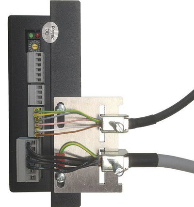
Critical factors also include an unacceptably small cable bending radius, which can lead to breakage of internal conductors, and the absence of expansion loops on moving parts of robots. Damage to connectors due to excessive wire tension leads to intermittent contact loss.
To ensure reliable data transmission, you must adhere to basic installation rules:
- Separation of routes. Signal and power cables must be laid in separate metal trays at a distance of at least thirty centimeters.
- Signal shielding. Use twisted-pair cables with overall and paired shielding made of tinned copper braid.
- Proper grounding. The cable shield must be grounded 360 degrees using dedicated EMC clips on the controller side.
- Interference protection. Install ferrite rings and filters on the power outputs of frequency converters.
- Clamping arrangement. It is essential to use strain-relieving cable glands.
Mistake #5: Ignoring Environmental Conditions
If a sensor is used while ignoring the actual environmental conditions, it will quickly stop working because of insulation failure or mechanical obstruction.
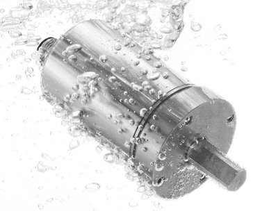 The entry of dust and abrasives into the optical unit leads to the obstruction of light from the LED and loss of signal strength. The ingress of moisture, cooling fluids, and oils causes short circuits on the circuit board and rusting of the metallic elements. Working in conditions of high vibration, without appropriate vibration absorption, will break soldering connections.
To prevent exposure to negative factors, it is necessary to select the correct enclosure protection class:
- IP65. Complete protection against dust ingress and protection against jets of water from any direction.
- IP67. Protection against temporary immersion in water to a depth of one meter.
- IP69K. Maximum protection against high pressure and high temperatures during intensive equipment cleaning.
In aggressive environments, additional protective covers, oil seals, and systems for supplying excess dry air into the device enclosure should be used.
Mistake #6: Incorrect Electrical Configuration
Mistakes in aligning the electrical properties of the sensor and the input of the PLC can result in a failure of the system or burn out the output sections.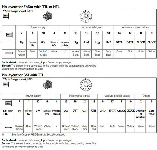
Use of a power supply that goes beyond the limits, or polarity reversal without the built-in diode, can damage the internal electronics immediately. Use of long communication lines will lead to supply voltage drop, and hence, the re-booting of the sensor in the moments of maximum load.
Selecting an inappropriate output stage type prevents correct data reading. The various types of signals and protocols must comply with the established standards of connection, which are as follows:
- TTL. It produces a differential RS-422 signal of 5 volts, which guarantees effective noise immunity through long-distance transmission.
- HTL. The voltage levels utilized are between 10 and 30 volts, and interference is minimal up to moderate distances.
- SSI. A synchronous serial interface that is used in absolute sensors and requires strict timing specifications.
- BiSS. An advanced technology that allows transfer of information in real-time and has built-in CRC.
- EnDat. A reliable digital technology introduced by Heidenhain used in precision servomotors.
Just before switching the electricity on for the first time, one should check the load capacity, the line impedance matching (the ends of the bus should be fitted with 120-ohm terminators), and the voltage range.
Symptoms of Poor Encoder Installation
Problems caused by improper installation manifest themselves through a number of characteristic technical symptoms. Recognizing these signs early on can prevent serious accidents.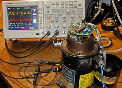
Poor installation can cause position feedback instability, with the current coordinate value "floating" or jumping while the shaft position remains constant. Missed pulses lead to cumulative errors over long periods of machine operation. Sudden drive stops due to lag errors often indicate short-term signal loss due to connector vibration.
Increased noise and vibration in the area where the device is installed clearly indicate shaft misalignment or bearing failure. Messages about digital communication failures are usually associated with high levels of electromagnetic interference or damage to the cable shield.
Fault diagnostic summary table:
|
Symptom |
Possible Cause |
Recommended Solution |
|
Missed pulses |
Electrical noise |
Improve shielding and cable routing |
|
Position errors |
Shaft misalignment |
Realign shaft and coupling |
|
Encoder overheating |
Incorrect installation |
Inspect mounting and operating conditions |
|
Communication errors |
Wrong wiring or protocol |
Verify electrical connections |
|
Premature bearing failure |
Excessive shaft load |
Install a flexible coupling |
Installation Checklist Before Startup
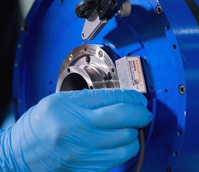 Before you will connect power and perform commissioning, you should conduct a comprehensive check of all components according to the following checklist:
- Alignment check. Shaft alignment has been checked with a dial indicator or laser.
- Coupling installation. The coupling has been tightened to the specified tightening torque.
- Enclosure fastening. The tightening of the clamping flange or mounting bracket has been checked.
- Cable routing. The signal cable is separated from the power wiring.
- Shield grounding. The cable shield is grounded at one or both ends in accordance with the EMC instructions.
- Electrical circuits. The voltage and polarity of the power supply have been checked.
- Communication parameters. The protocol and interface parameters are consistent with the PLC.
- Manual rotation. The drive shaft rotates freely without binding or abnormal noise.
- Enclosure protection. The IP protection class and seal condition have been confirmed.
- Functional test. A trial run at low speed was successful.
Best Practices for Long-Term Encoder Reliability
Ensuring long-term and trouble-free operation of feedback sensors requires the implementation of a preventative maintenance program:
- You must regularly visually inspect mechanical fasteners and the condition of the coupling.
- Regularly checking the tightening torque of screws and the absence of play will prevent the development of destructive vibrations.
- Cable routes should be inspected for insulation abrasion, fractures, and exposure to aggressive chemicals.
- Vibration monitoring with portable vibration analyzers allows you to detect bearing wear at the earliest stage, long before they become completely seized.
- Periodic testing of grounding quality and insulation resistance protects electronic components from static electricity.
Field insight. “Most encoder failures don’t begin inside the encoder – they start with installation or maintenance issues that go unnoticed.”
How to Install an Encoder for Reliable Performance
To achieve maximum reliability and accuracy when installing a feedback sensor, engineers are advised to follow a strict sequence of steps:
- Study the mechanical kinematics. Before beginning installation, you must carefully study the drive drawings, estimate the maximum axial and radial displacements of the motor shaft during heating, and determine the maximum dynamic accelerations.
- Check the alignment of the mating shafts. Install a dial indicator on the drive housing and measure the radial and axial runout of the shaft. Deviations should not exceed the values specified in the sensor's data sheet (usually no more than two hundredths of a millimeter).
- Select and professionally install the coupling. Secure the expansion coupling to the shaft without using excessive force. Do not allow the coupling to operate at the limit of its compensation capabilities, as this will reduce its rigidity.
- Check electrical compatibility. Before connecting the wires, use a multimeter to ensure there are no extraneous potentials on the equipment housing. Check that the connection diagram matches the connector pinout. Establish a noise-protected line. Lay the signal cable in a grounded metal sleeve or separate tray. Ensure reliable electrical contact between the cable shield and the control cabinet enclosure.
- Conduct comprehensive testing before commissioning. Perform a test run of the drive at minimum speed, monitoring the pulse shape with an oscilloscope. Ensure there are no gaps or noise in the phase channels.
- Create a maintenance chart. Record the initial operating parameters (vibration level, enclosure temperature) in the equipment datasheet for subsequent comparative analysis during operation.
Expert insight. “I never assume an encoder will work simply because it’s mounted. I verify alignment, wiring, signal quality, and operating conditions before the machine enters production.”
FAQ
How do I know if an encoder is installed correctly?
Proper encoder installation is confirmed by free and smooth shaft rotation by hand without noticeable binding, play, or extraneous noise. Measuring instruments should record a minimum level of radial and axial runout, not exceeding the tolerances specified in the technical data sheet. When power is applied and a test run is performed, the oscilloscope or controller displays a stable rectangular signal without chatter or missing pulses. The device housing should not exceed normal temperatures or be subject to strong vibration during prolonged operation under load. The final criterion is the absence of cumulative positional error and misalignment errors in the control program.
Can shaft misalignment damage an encoder?
Shaft misalignment is one of the most common causes of premature mechanical failure of an encoder. The resulting radial and axial loads overload the bearing assembly, causing accelerated ball wear and cage failure. Constant bending moments are transmitted to the internal shaft, leading to micro-shifts in the reading elements. In optical models, this eventually causes physical friction and breakage of the glass coding disk against the internal elements. As a result, the device loses accuracy, begins to overheat, and completely fails within a short period of time.
Why is electrical shielding important for encoder cables?
Low-current sensor signals are extremely sensitive to external electromagnetic fields generated by industrial equipment. High-quality electrical shielding made of copper braid absorbs induced high-frequency interference and directs it into the ground loop. Without it, phantom voltage spikes occur in the pulse channels, which the controller interprets as false pulses. This inevitably leads to distorted position data and constant malfunctions of the entire motion control system.
Should encoder cables run next to motor power cables?
Laying signal lines in the same tray or conduit as motor power lines is strictly not recommended, as proper cable routing is critical to stability. Power lines of frequency converters generate powerful pulsed interference due to high voltage and pulse-width modulation. Crosstalk easily penetrates sensitive measuring circuits and disrupts phase channel readings. For reliable operation, these lines must be separated by at least thirty centimeters or metal partitions must be used. If separation is not possible, only crossing lines at strictly right angles is permitted.
What causes unstable encoder signals?
The problem manifesting as unstable encoder signals is usually caused by a combination of mechanical and electrical factors. Electromagnetic interference from inverters and poor grounding lead to distorted pulse shapes. Mechanical vibrations from a flexible bracket cause optical bounce and jitter in the read head. Other causes include power supply voltage drops on long lines or slippage of a loose coupling. Dust and moisture accumulation inside the optical block also reduces signal amplitude to critical levels.
How often should an encoder installation be inspected?
An initial encoder maintenance inspection should be performed as part of routine maintenance every three to six months. Regular inspections include checking the tightening torque of the mounting screws and coupling clamps. Engineers also check for cracks in the cable sheath and the secure connection of the grounding terminals. In heavy-duty applications with high vibration, shaft runout measurements and coupling inspections should be performed monthly. Preventive monitoring allows us to detect loosening of mechanical components before an emergency line shutdown occurs.
Can incorrect coupling selection reduce encoder life?
Incorrect coupling selection directly impacts the mechanical life of the entire measuring unit. A rigid coupling, even with the slightest misalignment, transfers the entire bending load to the encoder shaft, quickly damaging the bearings. A coupling that is too soft or of poor quality causes torsional vibrations and backlash, reducing positioning accuracy. A properly selected compensation element smooths out radial displacements and protects the device from dynamic impacts. An incorrectly selected coupling type can reduce the device's service life from several years to a couple of weeks.
What IP rating should I choose for harsh industrial environments?
The correct IP rating selection depends on the aggressiveness of the environment: for operation in dusty, oily, or coolant-containing environments, choose models of IP65 or higher. The IP65 standard guarantees complete sealing against dust and resistance to water jets from any direction. If equipment is subject to regular high-pressure cleaning, it is recommended to install sensors with an IP67 or IP69K protection rating. Additionally, in harsh environments, double shaft seals and protective metal enclosures are used. For outdoor installations, it is also important to consider the temperature range and corrosion resistance of the housing materials.
Do absolute encoders require different installation procedures than incremental encoders?
From a mechanical perspective, absolute encoder installation is based on the same alignment and clamping rules as incremental models. However, absolute encoders require a mandatory electrical or software zero-setting procedure during commissioning. When connecting digital interfaces such as SSI, BiSS, or Fieldbus, strict bus topology and shielding requirements must be observed. Phasing or addressing errors in the absolute encoder lead to incorrect multi-turn coordinate readings during startup. Otherwise, the requirements for cable quality, shaft alignment, and interference protection remain identical.
What's the most common encoder installation mistake?
The most common encoder installation mistake is ignoring shaft alignment tolerances and rigidly coupling the encoder without taking compensation into account. Installers often tighten coupling screws by eye, hoping that the flexible element will conceal any misalignment. The second most common problem is running the low-current sensor cable in the same conduit as the engine's power wires. Both of these errors lead to either rapid mechanical failure or constant phantom electronic malfunctions. Careful preliminary alignment and separation of the cables prevents up to 90 percent of all problems.