0 Items / €0.00
29.10.2020
Quadrature encoder is an incremental sensor with output signals in the form of square waves.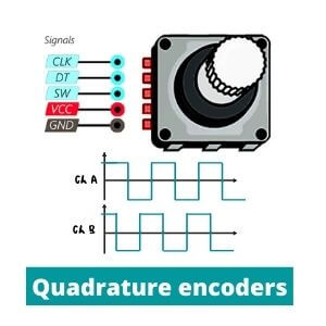
CONTENTS:
Quadrature rotary encoder is the most common used device for angular rotation measurement. Let's figure out how these types of signals arise?
Read also: What is difference between incremental and absolute encoders?
There are a number of different encoder types with operational principles. However, the main principle of signal interaction remains very similar. Let's consider the appearance of pulses using the example of an optical quadrature encoder.
Rotary sensor has a disk (wheel) that is attached on a shaft. Their special marks are located on its surface in contact zone. Such labels are transparent, and the disk surface between them is made of impenetrable material.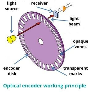
In the case of a linear quadrature encoder, a scale replaces the measuring disk. Special reader (slider) travels along it. The main working principle remains all the same.
A quadrature encoder pulse in the form of a light beam comes from the source and, depending on the opposite type of surface (solid or opaque), falls or does not fall into the receiver (detector).
Quadrature incremental encoder has two separate pins on the disk where this process takes place. There are sensing channels which act like signal detectors. They are commonly called as channel A and channel B. These points have separate inputs and wiring. Therefore, the device have two signal receivers in the one particular moment.
Incremental measurement also requires a starting point. So, there is a Z channel that displays the start (zero) position.
Depending on whether the light hits a transparent mark or an opaque surface, the receiver captures or does not capture the signal. This can be graphically represented as two diagrams with a rectangular form also called square waves.
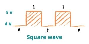 Rotary quadrature encoder is digital IC (integrated circuit) so it uses a binary code. Square waves show digital signals at a high (1) and a low (0) state. Binary code is needed to transfer data through interfaces (USB for example) and protocols to control systems. We have already described the main types of data transfer here: Parallel vs Serial interface.
The picture shows a diagram with the operation of the encoder with 5V power supply. As you can see the lines are shown a low 0V (grounding) and high 5V status.
The number of pulses per one full disk revolution depends on the number of marks on its surface. This principle is a basic definition of encoder resolution. Thus, two output signals characterize the number of pulses for a certain time. Using these values, a control system can determine the angular velocity, distance and acceleration.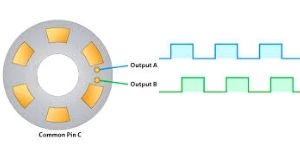
Let's explain the basic concepts in the diagram. First, we have the concept of a cycle, which consists of 360 electrical degrees (marked C). The letter P is denoted by the pulse width. This is the number of electric degrees when the pulse reaches its highest point during one cycle. Finally, the phase in our case is the difference between the centers of the pulse widths of both lines.
Sometimes you may meet graphs with channels (U, V, W). These integrated switching signals simulate hall sensors. Such feature is common for quadrature encoders that are used in feedback of brushless DC motors.
Nevertheless, the wheel can rotate in both directions. How to determine what is spinning now? It’s quite simple. That is why you need two points and two lines instead of one. As you can see both pins are placed in sequence.
Hence, when you look at the two graphic lines at the same time, you can see that they are also slightly shifted. Output channels A and B are specially placed on the disk at certain distance so that their phases on the graph are shifted by 90 degrees. The cycle is also divided into 4 equal parts for ease of calculation. In each of these parts, the graphs are in unique positions from each other.
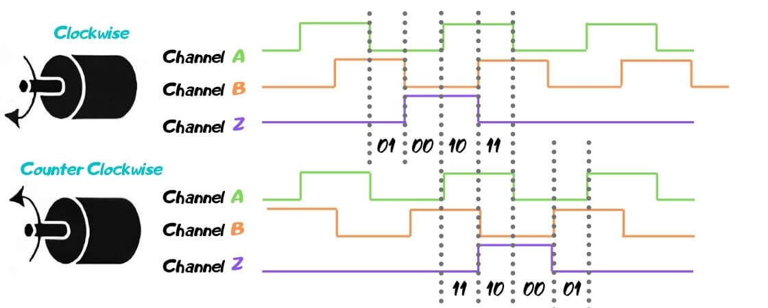
If the encoder moves forward (clockwise), line A is at the highest point (1) and channel B is at the lowest point (0). We get a combination of 1 and 0. The next one is 11, 00, etc.
If we start from the same point in a different direction (counterclockwise), we see that first the line will be at the highest point (11) and then the following combinations are: 01,00, etc.
Thanks to the Quadrature encoder interface (QEI) by comparing the difference of points in each period, we get a unique code that indicates the order in which combinations of digits are received. The microcontroller or position counter can determine which direction the disc is spinning by analyzing such data. After the decoding, such information enters the control systems or is displayed in the usual format on the display. The presented system is one of the simplest. We offer a large catalogue of eltra quadrature encoders. Check it out!